Lined Fittings
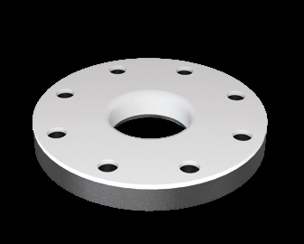
Lined adapter flange, NB 1/2" to 16", 12–36.6 mm
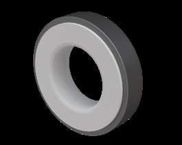
Lined adapter flange with a full-face fluoropolymer facing — mates a lined line to unlined or dissimilar equipment. NB 1/2" to 16" in PTFE, PFA and FEP.
| Product type | Lined full face adapter flange |
|---|---|
| Body / steel grade | IS 2062 plate / ASTM A 105 |
| Lining material | PTFE / PFA / FEP |
| Liner standard | ASTM D 1457 / ASTM D 4894-19 (PTFE), ASTM D 3307 (PFA), ASTM D 2116 (FEP) |
| Lining options | Virgin or anti-static (conductive black) PTFE to ASTM D 4894 & D 4895, PFA to ASTM D 3307, FEP to ASTM D 2116 |
| Flange standard | ASME/ANSI B16.5 |
| Flange class | Class 150 standard; Class 300 on request |
| Size range | NB 1/2" to NB 16" |
Product overview
A full face adapter flange carries the fluoropolymer across the whole flange face rather than just the raised face. That makes it the correct transition piece between a lined line and equipment with a flat-faced or dissimilar flange — a plastic vessel nozzle, an FRP line, a rubber-lined item — where a raised-face joint would concentrate load and crack the mating flange.
The flange is cut from IS 2062 plate or ASTM A 105 and drilled to ASME/ANSI B16.5 Class 150. PTFE, PFA and FEP are all marked applicable across the full NB 1/2" to 16" range, at the same thicknesses as the lined blind flange.
Features
Benefits
Applications & industries
Technical data
Figures below are for this product only — every item in the range carries its own dimension table.
| Product type | Lined full face adapter flange |
|---|---|
| Body / steel grade | IS 2062 plate / ASTM A 105 |
| Lining material | PTFE / PFA / FEP |
| Liner standard | ASTM D 1457 / ASTM D 4894-19 (PTFE), ASTM D 3307 (PFA), ASTM D 2116 (FEP) |
| Lining options | Virgin or anti-static (conductive black) PTFE to ASTM D 4894 & D 4895, PFA to ASTM D 3307, FEP to ASTM D 2116 |
| Flange standard | ASME/ANSI B16.5 |
| Flange class | Class 150 standard; Class 300 on request |
| Size range | NB 1/2" to NB 16" |
| Temperature range | Continuous service to 260 °C (PTFE melting point 327 °C, PFA 306 °C, FEP 260 °C) |
| Pressure rating | ASME/ANSI B16.5 Class 150 flanges as standard; Class 300 available on request |
| Manufacturing standard | ASTM F 1545 |
| Spark testing | Every lined component spark tested at 5000 × E volts (E = liner thickness in mm), to a maximum of 15 000 V |
| Hydro testing | Hydrostatic or pneumatic test according to the lining technique; hydrostatic test on components with vent holes |
| Inspection | Dimensional and visual examination of liner and steel parts — weld aspect, overall dimensions, collar size, liner thickness, surface flaws and paint thickness |
| Vent holes | 3 mm diameter vent holes — one per fitting; spools under 500 mm get a single central hole, spools over 500 mm get two holes about 150 mm from each end |
| External protection | Zinc epoxy primer, minimum 60 μm dry film, over steel sand-blasted to SA 2.5 |
| Certification | EN 10204 3.1 mill certificates and FDA certification for the fluoropolymer available on request |
| Face type | Full face fluoropolymer facing |
| Size | Face to face L (±2) | PTFE | PFA | FEP |
|---|---|---|---|---|
| 0.5" | 12 | ✓ | ✓ | ✓ |
| 0.75" | 12.7 | ✓ | ✓ | ✓ |
| 1" | 14.3 | ✓ | ✓ | ✓ |
| 1.5" | 17.5 | ✓ | ✓ | ✓ |
| 2" | 19 | ✓ | ✓ | ✓ |
| 2.5" | 22.4 | ✓ | ✓ | ✓ |
| 3" | 23.9 | ✓ | ✓ | ✓ |
| 4" | 23.9 | ✓ | ✓ | ✓ |
| 6" | 25.4 | ✓ | ✓ | ✓ |
| 8" | 28.5 | ✓ | ✓ | ✓ |
| 10" | 30.3 | ✓ | ✓ | ✓ |
| 12" | 31.8 | ✓ | ✓ | ✓ |
| 14" | 35.1 | ✓ | ✓ | ✓ |
| 16" | 36.6 | ✓ | ✓ | ✓ |
All dimensions in mm. All three lining materials are marked applicable across the full size range.
FAQ
Whenever the mating flange is flat-faced or made from a brittle material — FRP, plastic, cast iron, glass-lined equipment. A raised face concentrates the bolt load on a narrow ring and can crack them.
Yes, when joining to a different material. The catalogue notes that lined components do not generally need a gasket between themselves, but one is required against a dissimilar material and where the joint is repeatedly assembled and dismantled.
Related products
Enquiry
Send the bore, the media, the temperature and pressure, and the flange standard you work to. Drawings and custom sizes welcome.
Send your requirement — media, temperature, pressure, dimensions — and we'll recommend the right product or fabricate it.
Talk to an engineer