Flanges, Inserts & Adaptors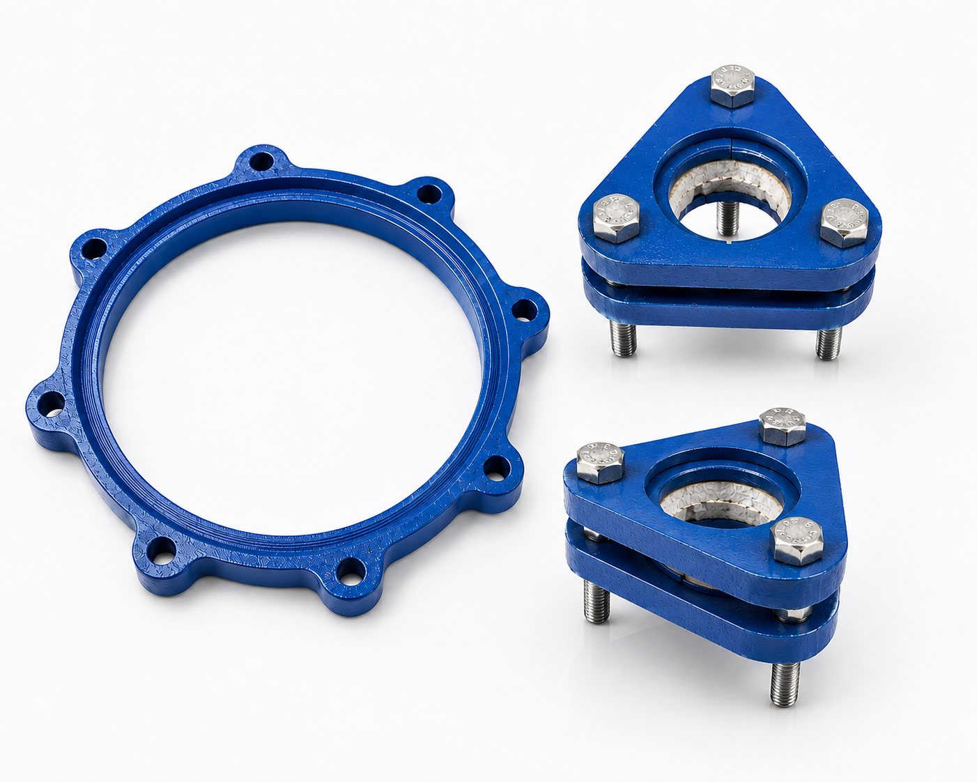
LSCF series, DN 15 to DN 600
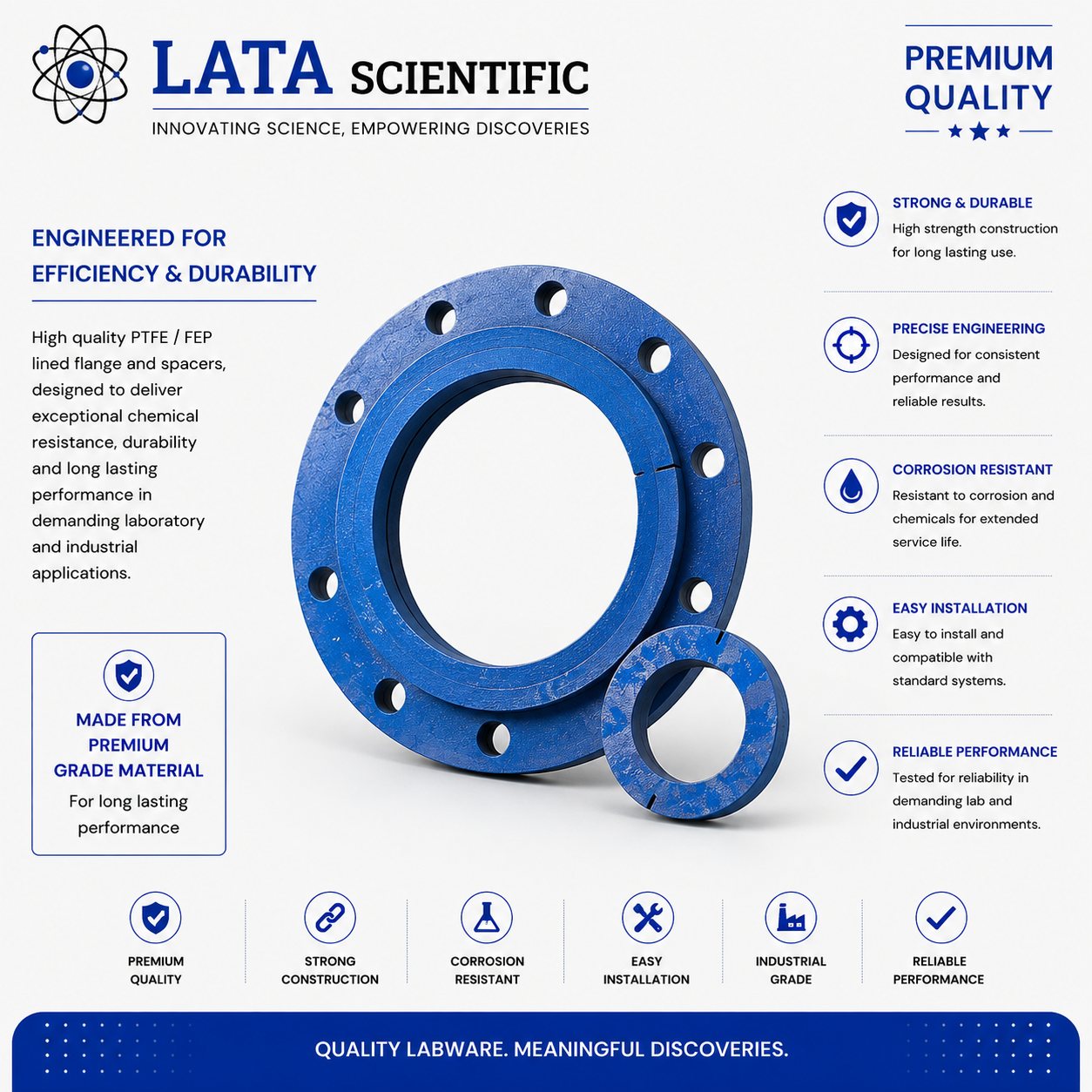
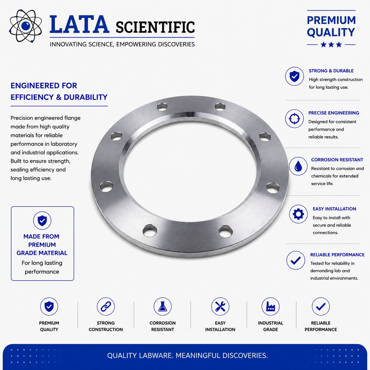
Cast iron backing flange for coupling a glass end to another glass end or to a bellow — used with inserts, DN 15 to DN 600 in three profile types.
| Product type | Backing flange for glass ends |
|---|---|
| Material | Cast iron |
| Used with | Inserts (LSCN series) |
| Couples | Glass end to glass end, or glass end to bellow |
| Nominal bore range | DN 15 to DN 600 |
| PCD range | 50 mm to 710 mm |
| Profile types | A, B and C, by size |
| Catalogue reference | LSCF series |
Product overview
The backing flange is used to couple a glass end to a glass end, or to a bellow. It is made of cast iron and is used with inserts — the flange takes the bolt load, and the insert bears on the glass bead so the glass is never clamped directly by metal.
This is the standard flange of the whole borosilicate pipeline system. Two of them, two inserts and a set of nut-bolts make one joint, which is exactly what the complete coupling supplies as a single reference.
The range runs DN 15 to DN 600 in twelve references, across three profile types — A, B and C — with the type changing as bore and flange thickness increase. Drilling is given directly in the table as PCD and n × d.
Features
Benefits
Applications & industries
Technical data
Figures below are for this product only — every item in the range carries its own dimension table.
| Product type | Backing flange for glass ends |
|---|---|
| Material | Cast iron |
| Used with | Inserts (LSCN series) |
| Couples | Glass end to glass end, or glass end to bellow |
| Nominal bore range | DN 15 to DN 600 |
| PCD range | 50 mm to 710 mm |
| Profile types | A, B and C, by size |
| Catalogue reference | LSCF series |
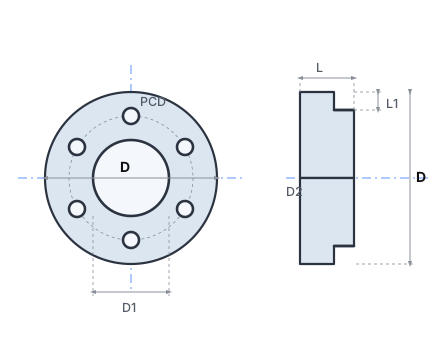
| Cat. Ref. | DN | D | D1 | D2 | PCD | n × d | L | L1 | Type |
|---|---|---|---|---|---|---|---|---|---|
| LSCF 07 | 15 | 70 | 30 | 35 | 50 | 3 × 6 | 10 | 6 | A |
| LSCF 1 | 25 | 95 | 43 | 51 | 70 | 3 × 9 | 10 | 6 | A |
| LSCF 1.5 | 40 | 110 | 58 | 66 | 86 | 3 × 9 | 10 | 6 | A |
| LSCF 2 | 50 | 120 | 70 | 81 | 98 | 3 × 9 | 12 | 8 | A |
| LSCF 3 | 80 | 155 | 101 | 112 | 133 | 6 × 9 | 12 | 9 | A |
| LSCF 4 | 100 | 200 | 134 | 148 | 178 | 6 × 9 | 12 | 9 | A |
| LSCF 6 | 150 | 275 | 186 | 196 | 254 | 6 × 9 | 15 | 9 | A |
| LSCF 9 | 225 | 350 | 260 | 282 | 310 | 8 × 11 | 28 | 7 | B |
| LSCF 12 | 300 | 425 | 342 | 363 | 395 | 12 × 11 | 34 | 7 | B |
| LSCF 16 | 400 | 525 | 467 | 476 | 505 | 12 × 12 | 22 | 12 | A |
| LSCF 18 | 450 | 630 | 537 | 557 | 585 | 12 × 14 | 37 | 7 | B |
| LSCF 24 | 600 | 755 | 643 | 690 | 710 | 12 × 14 | 50 | 5 | C |
All dimensions in mm, transcribed exactly from the catalogue page. n × d is the number of holes × hole diameter. Note that LSCF 07 is drilled 3 × 6 where the rest of the small sizes are 3 × 9, and that LSCF 16 returns to profile type A between two type B sizes — both are as printed.
FAQ
So that cast iron never bears directly on the glass bead. The insert is the split ring that sits between them and spreads the bolt load evenly around the bead.
This one couples glass to glass, or glass to a bellow — both sides use glass-standard drilling. The adaptor backing flange (LSCFA) is for coupling a glass end to a flange with a different bolt configuration, such as on a glass-lined reactor.
It follows the n × d column — 3 bolts up to DN 50, 6 from DN 80 to DN 150, 8 at DN 225 and 12 from DN 300 upward.
Yes — one on each glass end, with an insert each and a set of nut-bolts. That combination is catalogued as the complete coupling (LSCT).
Related products
Enquiry
Send the bore, the media, the temperature and pressure, and the flange standard you work to. Drawings and custom sizes welcome.
Send your requirement — media, temperature, pressure, dimensions — and we'll recommend the right product or fabricate it.
Talk to an engineer